It seems like everywhere you look these days you hear about new 3D printing technology. However, while the technology continues to evolve, 3D printing has actually been around a long time. As a matter of fact, Fluke has used 3D printing technology for prototyping for more than two decades.
"Our first 3D printer printed parts out of wax," says Terry Morey, Engineering Manager at Fluke. "Wax 3D printing was fairly limited, but it gave us the opportunity to design something on the computer, print it right away, and take it to a meeting so people could get a better idea of the concept we were proposing than by just looking at a 2D drawing."
Evolving 3D printing technology makes prototypes work harder
Today the wax printer is long gone, replaced by newer generation printers that produce more durable objects to tighter and tighter tolerances. Today Fluke uses two types of 3D printers.
Fluke's industrial designers use a Z-Corp printer that prints parts from plaster powder. After items are printed they are dried in an oven and coated with a penetrating superglue that soaks in and hardens the parts. This printer is used to produce solid models of instruments for evaluation by Fluke's industrial designers.
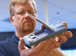
"The designers ask questions like 'Does it fit in your hand? Is the thumb close enough to turn the knob? Are the buttons so close together that when you put a finger on one, you actually push two?'" says Mark Nerby, CAE Engineer for Fluke and resident 3D printing wizard. "These solid models are also used to get initial feedback on the form and fit of a device from potential customers. The integration of 3D printing into our design process truly changed the way we design things because we can print out a model overnight, analyze it, get feedback, make subtle changes, and reprint it within a matter of a few days."
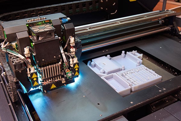
Once the conceptual prototype has been modified and approved, the revised CAD file is sent to Fluke's Eden printer, which prints hollow cases complete with buttons and knobs. It prints parts individually in hard plastic, clear plastic, and a soft rubberized material. The parts are printed with a resin and cured with ultraviolet light for durability. The Eden printer can print the case out of hard plastic, with a knob made of a different color and type of plastic, and a knob shaft of still another type of plastic.
Mechanical engineers use these cured resin prototypes to analyze all aspects of the product, from inserting a circuit board to see how the parts fit, to working with the knobs and buttons, to inserting the model into a holster (which might be a prototype).
Functional prototypes faster and cheaper
The old adage that says "Good, cheap, or fast—pick any two" doesn't apply here, because with 3D printing you can have all three. However, "cheap" refers to the cost, not the quality. "3D printers and materials are evolving fast and improving tolerances to the point where prototype quality is getting much closer to final product quality," says Morey.
As for cost, parts produced on the Eden printer run about 65 cents per cc or $10 per cubic inch, and parts made on the Z-Corp printer are about one-third of that cost.
When it comes to delivery speed, 3D printed prototypes are light years ahead of traditional prototyping methods. "Most parts take only 12 to 15 hours to print and a few more hours to clean up and cure," says Nerby. That saves weeks over traditional prototyping methods.
For example, Fluke builds test fixtures or nests to hold a part in a certain way for testing. Before 3D printers, those nests took a couple of weeks to build in the machine shop. "Today we send a file to 3D printing and the next day we'll have a fixture in hand," says Jeff Worones, Mechanical Engineer at Fluke. And, because each design iteration can be produced quickly and for a minimal cost, it is more practical to explore more concepts and refine those initial concepts before presenting them.
Expedited design
"We send the CAD file of the mechanical design to our circuit board layout group with instructions like 'we need screw bosses here so don't put any components there,'" says Worones. "They send us back a populated circuit board so we can see every component on the board and check the fit and function within the case. We even do some rough testing to determine whether there is any interference between the components."
Multiple versions of that assembled prototype are sent to a cross-functional project team of planning, test, and manufacturing engineers, who often are located all over the globe. Working with the physical models and the CAD image in online conferences, team members review the virtual and physical models from every angle and make any additional modifications necessary.
The 3D printed prototypes can also be used to set up the manufacturing cell. "We're doing more concurrent engineering where the manufacturing group sets up the manufacturing cell and tests it before the production parts are ready, which allows us to work out a lot of the variables ahead of time," says Worones.
Making tools for small part runs
Recently the Fluke Plastics Group came to Morey with a request for a 500 quantity of a small plastic part that was originally built by a company Fluke acquired some years back. All the engineers had to work from was a 1979 paper drawing. Brian Aikins, Mechanical Engineer at Fluke took on the challenge. He re-created the part and then Jeff Worones developed a 3D printed tool in plastic that could be used to produce small quantities.
"The printed plastic tool is so inexpensive to print that we can print multiple copies of it, and if we only got 30 parts out of each one, that's okay; it's still much cheaper than spending thousands of dollars and waiting 10 to 12 weeks for a steel tool that could be used for 20,000 parts or more, when we only need 500," Morey says.
Another advantage of printing a tool is that it uses an additive manufacturing process where only the material needed to make the part is applied. Traditional subtractive manufacturing starts with a block of metal and removes material to create the form for the part. "The more material you start with the more it costs, and when you remove that material you're basically throwing away money," says Worones. "With 3D printing you can put a hole in the middle of something and not have to pay for the material that is removed, which keeps costs down and creates less waste."
Printing the future in 3D
There is a growing belief that eventually many products, or at least product components, will be printed rather than manufactured on an assembly line. That day is a ways off, but a more immediate possibility is that the metal tools used to form the plastic parts that make up Fluke instruments will eventually be printed rather than machined. This will likely be done with a laser sintering printer that fuses metal powder layer by layer into a solid part using a laser beam. The resulting tool, printed from a CAD file, would reduce the tool development cycle from 10 to 12 weeks to a few days.
"With 3D printed tools you could take two or three months out of a year-long project and cut out a significant amount of capital expense plus get to market a quarter sooner," says Morey.